1、概述
1、Overview
PGS-12/24/40.5型户外柱上SF6绝缘负荷开关,适合用于柱上安装,额定电压12/24/40.5kV,额定电流400A、630A、50/60Hz配电网开断、关合电力系统中的负荷电流、过载电流,能够自动将发生故障的配电线路区段隔离开。开关带有新技术的电子控制器,可以手动操作、电动操作和远距离操作。电子控制器装在不锈钢箱体内,能够适合各种气候条件下使用。此外,箱体内还可安装了有线和无线调制解调器,可以实现远距离监视和控制。简单的柱上安装布置方便、快速,降低施工成本。
Column installed insulation load switch, typePGS-12/24/40.5,is suitable for the rated voltage 12/24/40. 5kV,rated current 400A、630A、50/60Hz power grid open circuit、load current in closed Power system、overload curren. This load switch can separate those broken distribution line automatically.
With the latest technology, it has the newest electronic controller.The switch can be used by manual operation, electric operation and operation from a long distance. Electronic controller is installed in a stainless steel cabinet which is suitable for using under all kinds of climatic conditions. In addition, there are some wired and wireless modem installed in the cabinet through which it can realize the remote monitoring and control. Simple installation on column is convenient, fast, and also can reduce the construction cost.
2、标准使用条件
2、The standard conditions of use
此SF6气体负荷开关适应运行条件:
operating conditions for SF6 gas load switch to adapt to:
2.1 环境温度
2.1 Ambient temperature
2.1.1 周围空气温度:上限+50℃,下限-40℃。
2.1.1 Ambient air temperature: upper limit +50 ° C, lower limit of -40 ℃.
2.1.2相对湿度:100%
2.1.2 Relative Humidity: 100%
2..2海拔不超过1000m;2000m;3500m。(按用户订货时提出要求。不提出为常规1000m要求。)
2.2 Elevation does not exceed 1000m;2000m;3000m
2.3 风压不超过700pa(相当于风速34m/s)。
2.3 The pressure does not exceed 700pa (equivalent to wind speed of 34m / s).
2.4 地震烈度:8度。
2.4 Earthquake intensity: 8 degrees.
2.5 安装场所:没有火灾、爆炸危险,无化学腐蚀及经常性剧烈震动。
2.5 Installation site: No fire, no explosion hazards, no chemical corrosion and recurrent severe vibration.
2.6 污秽等级:Ⅲ类、Ⅳ类。
2.6 Pollution class: class III, class IV.
3 特征
3 FeaturesFeatures
3.1 SF6气体绝缘
3.1 SF6 gas-insulated
3.1.1 SF6气体是无毒、不可燃的电绝缘气体,具有极佳的灭弧特性。
3.1.1 SF6 gas is a kind of nontoxic, nonflammable and electrical insulating gas. It has the excellent characteristic of arc extinction.
3.2 套管多样性
3.2 Drivepipe with large diversity
3.2.1 除了标准陶瓷套管外,还可以提供多种方案,包括在环氧设备套管上的橡胶绝缘子。
3.2.1 In addition to the standard ceramic drivepipe, we can also provide a variety of solutions, including rubber insulators used in the epoxy resin filling equipment
3.3 可见的断开/闭合状态
3.3 Visible open / closed status
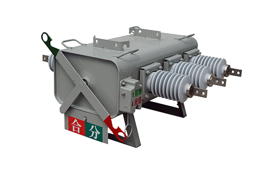
3.3.1 站在地上很容易看清用颜色标记的主触点位置指示器(绿断开;红 闭合)。该指示器与主触点驱动轴总成直接连接,确保准确显示触点状态。
3.3.1 It is easy to see the main contact position indicator which is color-coded just standing on the ground (Green - off; red - closed). The indicator is directly connected with the main contacts of the drive shaft assembly to ensure accurate display of contact states.
3.4 快速操作
3.4 Quick operation
3.4.1 采用弹簧储能的操作机构确保快速合闸与分闸操作(少于100毫秒)。
3.4.1 operating mechanism with spring energy to ensure a quick closing and opening operation (less than 100 milliseconds).
3.5 可以实现遥控
3.5 Can realize remote control
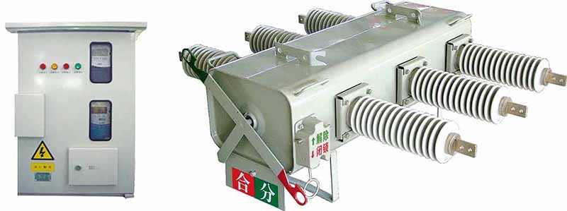
3.5.1 备有电子控制器,既可就地操作,也可用FTU界面实现主控台操作。
3.5.1 It is equipped with electronic controller, fit for in situ operation as well as FTU interface console operation.
3.6 坚固耐用的开关
3.6 Rugged switch
3.6.1 开关采用经过验证的坚固耐用、抗腐蚀的材料(军舰专用304L不锈钢钢板)做成,确保有很长的使用寿命(20年),并能实施一系列操作,具有柱上设备理想的特性。
3.6.1 The switch is made of proven durable, corrosion-resistant materials (special used in warships 304L stainless steel plate)which ensures that there is a very long service life (30 years), and can be implement a series of operations.It has the ideal characteristics as a column equipment.
3.7 标准
3.7 Standard
3.7.1 每一开关出厂前已经充装好SF6气体,密封处理,并按IEC60265-1(1988)、GB3804-1990标准进行试验。
3.7.1 Each switch before leaving the factory has been filled with SF6 gas, sealed, and test according to IEC60265-1 (1988), GB3804-1990 standard.
4. 类型与额定值
4 Type and Rating
4.1 产品型号
4.1 Product mode

a. Type of operating mechanism (M-manual, A-electric Z-automatic)
b. Derived product symbol (L-. Cable, outlet B-arrester)
c. Rated Current (A)
d. Rated voltage (kV)
e. Product Name (W-outdoor SF6 switch)
f.Corporate code (SP) Shanghai transmission and distribution electrical
4.3 PGS户外柱上SF6绝缘负荷开关的类型
4.3 Types ofPGS

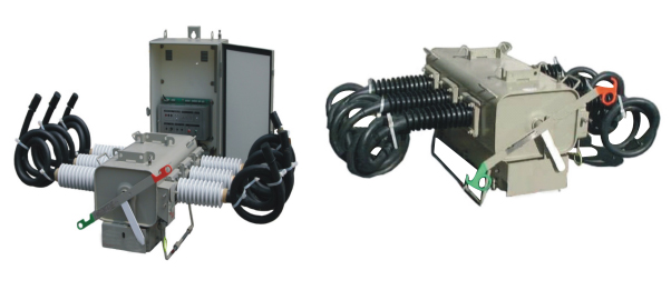
图1)陶瓷套管 – 模压电缆出线图2)橡胶分体套管 –模压电缆出线
Figure 1) ceramic bushing - molded cable outlet Figure 2) rubber split bushing - molded cable outlet

图3)橡胶一体套管 – 接线端子出线图4)带有避雷器
Figure 3) rubber bushing - terminal outlet Figure 4)with a lightning arrester


图5)陶瓷套管–接线端子出线
Figure 5) ceramic bushing - terminal outlet
4.4 参数额定值
4.4 Parameters ratings
表1
|
序号 |
名称 |
单位 |
数据 |
||||
|
产品型号 |
PGS-12 |
PGS-24 |
PGS-40.5 |
||||
|
1 |
额定电压 |
kV |
12 |
24 |
40.5 |
||
|
6/10/11 |
15/17.5/20 |
33/36/38 |
|||||
|
2 |
额定频率 |
Hz |
50/60 |
50/60 |
50/60 |
||
|
3 |
额定绝缘水平(所充SF6气体0.07Mpa / 20℃时) |
雷电冲击耐压 |
相间,相对地 |
kV |
75 |
125 |
185 |
|
断口 |
85 |
145 |
215 |
||||
|
工频耐压1min |
相间,相对地 |
kV |
42 |
64 |
95 |
||
|
断口 |
50 |
79 |
110 |
||||
|
4 |
零表压下的绝缘水平 |
工频耐压1min |
kV |
30 |
|
|
|
|
反相耐压1min |
30 |
|
|
||||
|
相电压5min |
9 |
|
|
||||
|
5 |
额定电流 |
A |
630(400) |
630(400) |
630(400) |
||
|
6 |
额定开断负荷电流 (0.07Mpa / 20℃时) |
A |
630(400) |
630(400) |
630(400) |
||
|
7 |
零表压下开断电流 |
A |
630(400) |
630(400) |
630(400) |
||
|
8 |
峰值耐受电流 |
kA |
50 |
31.5 |
31.5 |
||
|
9 |
额定短时关合电流 |
kA |
50 |
31.5 |
31.5 |
||
|
11 |
额定短时耐受电流 |
KA/s |
20/4 |
20/4 |
20/4 |
||
|
12 |
额定电缆充电开断电流 |
A |
25 |
25 |
25 |
||
|
13 |
额定线路充电开断电流 |
A |
16 |
16 |
16 |
||
|
14 |
额定闭环开断电流 |
A |
630(400) |
630(400) |
630(400) |
||
|
15 |
激磁电流 |
A |
21 |
21 |
21 |
||
|
16 |
额定电流开断次数 |
次 |
≥400 |
≥400 |
≥400 |
||
|
17 |
额定工作压力 |
Mpa |
0.07 |
0.07 |
0.25 |
||
|
18 |
每相主回路电阻 |
μΩ |
≤150 |
≤150 |
≤150 |
||
|
19 |
气体相对泄漏率 |
年 |
≤1% |
≤1% |
≤1% |
||
|
20 |
SF6气体水份含量 |
出厂交接值 |
ppm |
≤150 |
≤150 |
≤150 |
|
|
开关运行值 |
ppm |
≤300 |
≤300 |
≤300 |
|||
|
21 |
机械稳定性操作 |
次 |
6000 |
6000 |
6000 |
||
|
22 |
额定操作电压及辅助回路额定电压 |
V |
DC 220/ 110/48/24 |
DC 220/ 110/48/24 |
DC 220/ 110/48/24 |
||
|
AC 220/110 |
AC 220/110 |
AC 220/110 |
|||||
|
23 |
重量 |
M型 |
kg |
115 |
125 |
135 |
|
|
A型 |
135 |
145 |
155 |
||||
|
24 |
机构箱和控制器防护等级 |
IP44 IP54 |
|||||
|
25 |
安装方式 |
吊装式(悬挂式)/座式(卧式) |
|||||
Table 1
|
No. |
Name |
Unit |
Data |
|||||
|
Product mode |
PGS-11 |
PGS-24 |
PGS-38 |
|||||
|
1 |
Rated voltage |
kV |
11 |
24 |
38 |
|||
|
6/10/11 |
15/17.5/20 |
33/36/38 |
||||||
|
2 |
Rated frequency |
Hz |
50/60 |
50/60 |
50/60 |
|||
|
3 |
Rated insulation level(The filling SF6 gas 0.07Mpa / 20 ° C) |
(Lightning impulse withstand voltage) |
relatively |
kV |
75 |
125 |
185 |
|
|
Fracture |
85 |
145 |
215 |
|||||
|
Power frequency withstand voltage 1min |
relatively |
kV |
42 |
64 |
95 |
|||
|
Fracture |
50 |
79 |
110 |
|||||
|
4 |
Insulation level of zero gauge pressure.
|
Power frequency withstand voltage 1min |
kV |
30 |
|
|
||
|
RP-pressure 1min |
30 |
|
|
|||||
|
The highest phase voltage 5min |
9 |
|
|
|||||
|
5 |
Rated current |
A |
630(400) |
630(400) |
630(400) |
|||
|
6 |
Rated breaking load current (0.07Mpa / 20 ° C) |
A |
630(400) |
630(400) |
630(400) |
|||
|
7 |
breaking current under zero gauge pressure |
A |
630(400) |
630(400) |
630(400) |
|||
|
8 |
peak withstand current |
kA |
50 |
50 |
50 |
|||
|
9 |
Rated short time making current |
kA |
50 |
50 |
50 |
|||
|
11 |
rated short time withstand current |
KA/s |
20/4 |
20/4 |
20/4 |
|||
|
12 |
rated cable charging breaking current |
A |
25 |
25 |
25 |
|||
|
13 |
rated line charging breaking current |
A |
16 |
16 |
16 |
|||
|
14 |
rated closed-loop breaking current |
A |
630(400) |
630(400) |
630(400) |
|||
|
15 |
exciting current |
A |
21 |
21 |
21 |
|||
|
16 |
rated current breaking times |
Times |
≥400 |
≥400 |
≥400 |
|||
|
17 |
rated working pressure |
Mpa |
0.07 |
0.07 |
0.25 |
|||
|
18 |
Per-phase main circuit resistance |
μΩ |
≤150 |
≤150 |
≤150 |
|||
|
19 |
relative gas leakage rate |
year |
≤1% |
≤1% |
≤1% |
|||
|
20 |
SF6 gas moisture content |
Factory transfer of value |
ppm |
≤150 |
≤150 |
≤150 |
||
|
Switch running value |
ppm |
≤300 |
≤300 |
≤300 |
||||
|
21 |
operation of echanical stability |
times |
6000 |
6000 |
6000 |
|||
|
22 |
rated operating voltage and auxiliary circuits rated voltage |
V |
DC 220/ 110/48/24 |
DC 220/ 110/48/24 |
DC 220/ 110/48/24 |
|||
|
AC 220/110 |
AC 220/110 |
AC 220/110 |
||||||
|
23 |
Weight |
Type M |
kg |
115 |
125 |
135 |
||
|
Type A |
135 |
145 |
155 |
|||||
|
24 |
institutions boxes and controller protection class |
IP44 IP54 |
||||||
|
25 |
Type of Mounting |
The lifting type (suspended)/block (horizontal) |
||||||
5. 结构
5. Structure
5.1 开关与控制器外观(型号:PGS-12/24/40.5)
5.1 switch and controller appearance (Model:PGS-12/24/40.5)

连接示意图
Connection diagram
开关的外观与尺寸(见表2)
The appearance and size of the switch(see table 2)


(表2)(table 2)
|
外形尺寸Dimensions(mm) |
安装尺寸Installation dimentions(mm) |
套管爬距Casing creepage distance(mm) |
|||
|
|
A |
B |
C |
长×宽Long x width |
|
|
11Kv |
225 |
435 |
500 |
500×125(280) |
556 |
|
24kv |
300 |
435 |
500 |
500×125(280) |
840 |
|
38Kv |
350 |
435 |
500 |
700×125(280) |
1250 |